Royal University of Phnom Penh
Faculty of Engineering
Dep. of Telecommunication and Electronic Engineering
Smart Detecting Train Auto Control Gate
 |
| Project Smart Detecting Train Auto Control Gate |
Smart Detecting Train Auto Control Gate
I. Abstract
II. Introduction
- To learn about electronic components.
- To show the powerful of electronic components in automatically working.
- To understand the process in developing project and in reality
- To compare process in project and reality working.
- To know the designing of PCB by using software.
- To know about making a new PCB as Arduino.
- To show that we can making a controller PBC by our own selves.
III. Electronic Requirement
- Mini Servo x2
- ATmega328P x1
- Crystal 16MHz x1 and Capacitor Ceramic 22pF x2
- IR sensor (TCRT5000) x6
- LDR Sensor x1
- LED (Red x3, Greenx2, Yellow x2 and White x8)
- Resistor (10Kohm x7, 330ohm x 6 and 100ohm x2)
- Capacitor Ceramic (100nF x2)
- Capacitor Electrolyte 10uF x2
- Adapter DC 9 or 12V (1 - 1.2A)
- 12vDC Connector x1
- Switch 12v x1
- Terminal Block 2pins x1
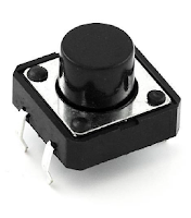
- Button x1
- Regulator (L7805) x1
- PCB (77mm x 72mm)
- Jumper wire
1. TCRT5000 IR Sensor
 |
| Figure 1: IR Sensor characteristic and Its working. |
2. Servo Motor
- It operates voltage from 4.8 – 6v
- Stall torque: 1.8 kg.cm (4.8V), 2.2 kg.cm (6 V)
- Operating speed: 0.1 s/60 degree (4.8 V), 0.08 s/60 degree (6 V).
 |
| Figure 2: Servo motor specification. |
3. ATmega328P
- Pin 1 is a reset pin to connect with a button.
- Pins 2&3 are the Rx and Tx pins.
- Pins 4 to 6 and 11 to 19 are the output digital pins.
- For pins 7&8 are the power pins of VCC and GND.
- For pins 9&10 are the connection pins of crystal with 2 capacitors.
- For pins 23-28 are the output analog pins.
 |
| Figure 3: Pins connection diagram for ATmega328P. |
IV. Methodology
1. Making Print Circuit Board(PCB)
 |
| Figure 4: Interface of Proteus ISIS design circuit schematic with v7.10. |
 |
| Figure 5: Interface of Proteus ARES design layout diagram with v7.10. |
- Proteus ISIS software v7.10: is used to draw the circuit diagram by connecting from any components which we necessary need for our project. It is also corporates to an ARES software program. See Figure 4 below for ISIS design.
- Proteus ARES software v7.10: used to draw a layout of PCB diagram which connect form ISIS schematic design. See Figure 5 below for ARES design layout diagram.
*Note: in these combining program, some package may not have in this software, so you need to draw it by manually.
1.2 PCB Hardware
 |
| Figure 6: Making PCB hardware with step by step. |
- For Fig6.1, show the printing out of the circuit drawing on a slipper paper by the Laserjet printer.
- Fig6.2, Iron that printed paper on the PCB board with a specific size.
- Fig6.3, Put the PCB which already ironed into acid and making vibrate it carefully.
- After we finish these 3 steps above then we need to apply all components to PCB board of each its position and then soldering it one by one. See Fig6.4&6.5.
V. Experiment
1. Program on ATMEGA328P Microcontroller
- a 16 MHz crystal,
- a 10k resistor, and
- two 18 or 22 picofarad (ceramic) capacitors.
1.1 Burning the Bootloader
 |
| Figure 7: Wire connection to burn the bootloader onto an ATmega328P with Uno Arduino. |
- Firstly, need to upload the ArduinoISP sketch onto an original Arduino board by select the board and serial port from the Tools menu that correspond to our board.
- Wire up the Arduino board and microcontroller as shown in the diagram of Figure7.
- Select "Arduino Duemilanove" from the Tools -> Board menu and then select to ATmega328.
- Select "Arduino as ISP" from Tools -> Programmer
- Run Tools -> Burn Bootloader
1.2 Uploading Using an Arduino Board
After ATmega328P has the Arduino bootloader on it, then we can upload programs to it by using the USB-to-serial convertor (FTDI chip) on an Arduino board.- To upload our code onto it, need to remove the microcontroller from the Uno Arduino board so the FTDI chip can talk to the microcontroller on the breadboard instead.
- Connect the RX and TX lines from the Arduino board to our ATmega328 on the breadboard as shown in Figure 8.
- To program the microcontroller, select "Arduino Duemilanove " from the the Tools > Board menu and select ATmega328, then upload as usual.
 |
| Figure 8: Wire connection to uploading sketches code to an ATmega328P on a breadboard. |
1.3 Algorithm of Project
 |
| Figure 9: Processing of Smart Detecting Train Auto Control Gate. |
 |
| Figure 10: Flow Char |
VI. Result
According to this project, there are two main parts, the smart detecting train system and auto night light system on this project. Let see the result of our full project’s demo is in the link below.
 |
| Figure 11: Result of Smart Detecting Train Auto Control Gate. |
VI. Conclusion
- Knew some electronic components characteristic and its specification.
- Understood the process in developing project and in reality.
- Know the comparing of process in project and reality working.
- Understood well about the designing of PCB by using Proteus software.
- Knew about how making a new PCB and boot-loading the ATmega328P as Arduino.


